| Chapter 11. Analysing sensor data | ||
|---|---|---|
 | Part II. Using Debrief |  |
Table of Contents
Debrief uses the following terms:
The sensor which recorded the data. Sensor data is grouped according to its sensor. This characteristic may be exploited by giving a unique sensor name to each track being recorded on a sensor - allowing tracks to be independently switched on and off.
This is an individual contact recorded on a sensor, a single bearing line reaching from the sensor location (origin) along the contact bearing to the contact range.
The sticky issue of whether to represent sensor data in absolute coordinates (where each line has its own origin) or whether to represent the data in relative coordinates (where the sensor origin is assumed to be the current ownship position) is managed through the ability to enter NULL fields for the sensor location.
Support for relative coordinates is provided for two reasons:
Some sensor data sources may genuinely not contain positional data - allowing relative coordinates will ease the workload in these instances.
In the submarine plot-lock process it is quite common to experiment with a number of track-shifts until the hull-mounted sensor bearing fans tie up with the other vessel. By keeping the sensor data separate to the vessel data, the existing sensor data-file can be dropped into Debrief with the updated vessel track-file, allowing the user to perform a visual qualitative check on the shift applied.
Note, it is not possible to define the sensor offset value in the REP file (see Section 11.1.4, “Sensor offset lengths editor”), it may only be defined from the Properties Window of Debrief NG. The value is stored safely when the Debrief plot is saved, however.
When Sensor Contact data is being plotted for a Sensor using relative coordinates, Debrief reflects a Sensor Offset distance for that sensor. The sensor offset distance denotes the horizontal distance between the centre of the centre and the attack datum of the host platform (+ve forwards, -ve backwards - so towed array data would be -ve). See the next section for more detail on the support for a shared library of array lengths. The location of the start of the sensor contact bearing line is calculated using the current value of course for the host platform and the sensor offset value.
![[Note]](images/note.gif) | Note |
|---|---|
|
Sensor data is typically added to a plot by dragging/dropping it from the view. If the dragged in datafile only contains cuts from a single sensor a dialog pops up give you chance to override the sensor name and color. If the file contains data from more than one sensor then they just quietly slip in. |
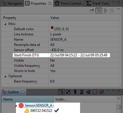
When viewing the properties view, you will see a Start/Stop DTG for the current sensor data time period. This entry is read only, but provides an at a glance method of viewing range set for the sensor data.

When examining a Sensor in the properties view, you will see that in addition to Sensor Offset, there is a 'Worm in the hole' (see Section 19.2, “Worm in the hole algorithm”). This is typically used for towed arrays, whereby the start of the sensor bearing line is located at the Sensor Offset distance back along the host platform track, instead of in a straight line behind the host.
Since Autumn 09 Debrief has supported a library of sensor offsets. These offsets are used to populate a drop-down list of lengths, used in support of specifying sensor offsets.
Somewhere on your network create a csv-formatted text file that stores two columns of data (as shown below). The first column is the platform/sensor name, the second column is that combination's array offset in metres (with -ve figures at the stern of the host platform). The file should end in a csv suffix, and is formatted as follows:
Sensor Name,Length (m)
Platform A,-45
Platform B,-124.6
Platform C,-551
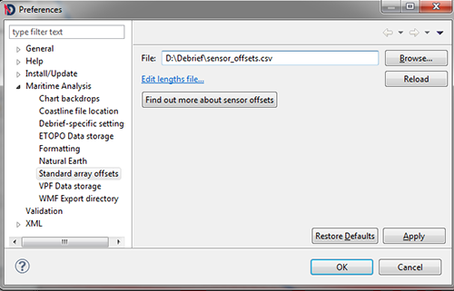
Then open the Debrief preferences page, and specify the offset file location using the Standard Array Offsets page

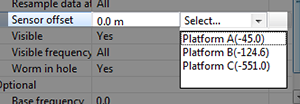
Once the standard offsets file has been specified, you are provided with a drop-down list of sensor offset distances when you view sensor data in the properties window:

![[Note]](images/note.gif) | Note |
|---|---|
|
Note, if you haven't got a sensor array offsets file assigned, you can still enter a value by hand. But, you do not need to specify the metres units. For an array offset of -400m, just enter -400. |
Sensor data is loaded into Debrief in REP files, just like any other Debrief data. The line format is one of:
;SENSOR: YYMMDD HHMMSS.SSS AAAAAA @@ DD MM SS.SS H DDD MM SS.SS  H BBB.B
 RRRR yy..yy xx..xx
;; date, ownship name, symbology, sensor lat/long (or the single word NULL),
 bearing (degs) [or the single world NULL], range(yds) [or the single world NULL], sensor name, label (to end of line)
or
;SENSOR2: YYMMDD HHMMSS.SSS AAAAAA @@ DD MM SS.SS H DDD MM SS.SS H BBB.B
 CCC.C FFF.F RRRR yy..yy xx..xx
;; date, ownship name, symbology, sensor lat/long (or the single word NULL),
 bearing (degs)  [or the single word NULL], ambigous bearing (degs) [or the
 single word NULL], frequency(Hz) [or the single word NULL],  range(yds) [or
 the single word NULL], sensor name, label (to end of line)
or
;SENSOR3: YYMMDD HHMMSS.SSS AAAAAA @@ DD MM SS.SS H DDD MM SS.SS H BBB.B  CCC.C
          FFF.F GGG.G RRRR yy..yy xx..xx
;; date, ownship name, symbology, sensor lat/long (or the single word NULL),
bearing (degs) [or the single word NULL], bearing accuracy (degs)
[or the single word NULL], frequency(Hz) [or the single word NULL],
frequency accuracy (Hz) [or the single word NULL], range(yds)
[or the single word NULL], sensor name, label (to end of line)
As you can see, unlike most other Debrief line formats, this format allows for NULL fields. Where the sensor latitude and longitude values are replaced by the single word NULL, Debrief plots this sensor contact using a relative origin. NULL values may also be provided for the ambiguous sensor bearing and/or detection frequency.
When (as described above) Debrief plots data using a relative origin, it follows the following procedure:
The first time the sensor contact line is plotted, it examines its parent track to find the vessel position nearest to (or greater than) the sensor contact DTG.
This position is then offset by a vector produced from the sensor offset value and vessel's current course.
The sensor contact then calculates the position of its far end relative to this origin